Hey, it’s Mark. Hope your summer is going great, and that you’re staying cooler than we are here in North Central Texas, USA. We are half-seriously looking for somewhere cooler to live, at least in the summer season. Any suggestions? Must be between the Arctic and Antarctic circles.
Today’s topic is:
POSITIONING A RASTER IMAGE AS AN UNDERLAY FOR CADDING
In two previous posts, I shared how to convert a paper sketch, print, or other type of physical drawing to raster file format (JPEG, for example) for inserting into an AutoCAD drawing. Then in the next post we inserted that raster image into an AutoCAD drawing to use as an underlay for CADDing.
If you’d like to review those earlier posts, here are links to them:
- Converting a paper print, drawing or sketch to a raster file: CLICK HERE
- Inserting the raster file into a DWG file: CLICK HERE
I have also created a video tutorial of today’s topic (this post) and it is available on my YouTube channel. To see it, GO TO VIDEO on YouTube, or just view it below.
Now we will discuss how to position the image properly in the CAD model space. The image will usually need to be scaled, and it will often need to be rotated.
Scaling and rotating are separate operations in AutoCAD. Usually it’s best to do the rotation operation first. The reason for this is that the scaling procedure works best if the points that we use for reference in setting the scale factor have an orthogonal relationship to each other. That is, the imaginary line between the points should be square with the computer screen. If the raster image is not rotated properly, those points will be out of alignment, making accurate measurement between the points more difficult.
This will become clearer later. First, let’s focus on rotating the image.
ROTATING AN IMAGE USING A REFERENCE ANGLE
The Rotate tool in AutoCAD is easy to use if you know the exact angle (say, 45 degrees) that you wish to rotate the selected object.

Positive and negative angles
Of course, it helps to remember that positive-number angles go counterclockwise in AutoCAD, and negative-number angles go clockwise.
However, if that angle is unknown, because it’s just related to a graphical line in the image, there is a great option within the Rotate tool called Reference.
One key tip before we begin: Use snaps carefully in doing this exercise. The safest way is to use snap overrides to ensure that AutoCAD is using the specific snap type that you specify.
First, let’s set up a center of rotation and two reference lines.
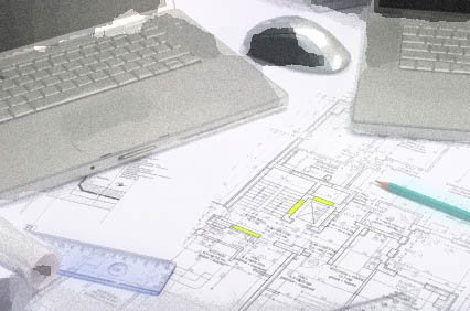
The screenshot below shows the JPEG image we inserted in the previous post, and you can see that it is in need of rotation. First we need to select a key corner of the sketch plan, at the end of a long, continuous wall (see the yellow circle).
I’ve drawn two CAD lines starting at this critical corner. The first one (yellow) is orthogonal and horizontal. The second line (red, dotted) is placed, with ORTHO turned OFF, on top of the long line of the sketch that we intend to become level after rotation. Note that the lines meet at a point which will become the base point for rotation (yellow circle).
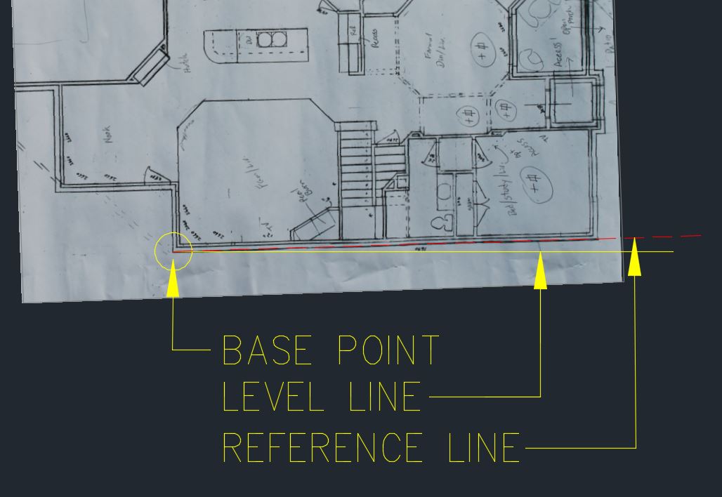
Reference lines and base point for rotation
Here is the sequence to rotate the image:
- Select the image by clicking on its frame. Make sure the grips are displayed at the corners of the image. Also select the red dotted reference line.
- Initiate the ROTATE command. On the keyboard, type RO [ENTER]; or in the ribbon go Home > Modify > Rotate.
- The command line tells you to specify your base point. Using an endpoint or center snap, click on the base point (in the yellow circle).
- The command line says to Specify the rotation angle or … Click on the Reference option in the command line, or you can type R [ENTER].

- Rotate command line with options
- Click on the base point (in the yellow circle) again.
- Click on the right endpoint (using endpoint snap) of the red dotted reference line.
- Click on the right endpoint of the yellow orthogonal line.
The image rotates into true level position, with the red and yellow lines overlapping (see screenshot below).
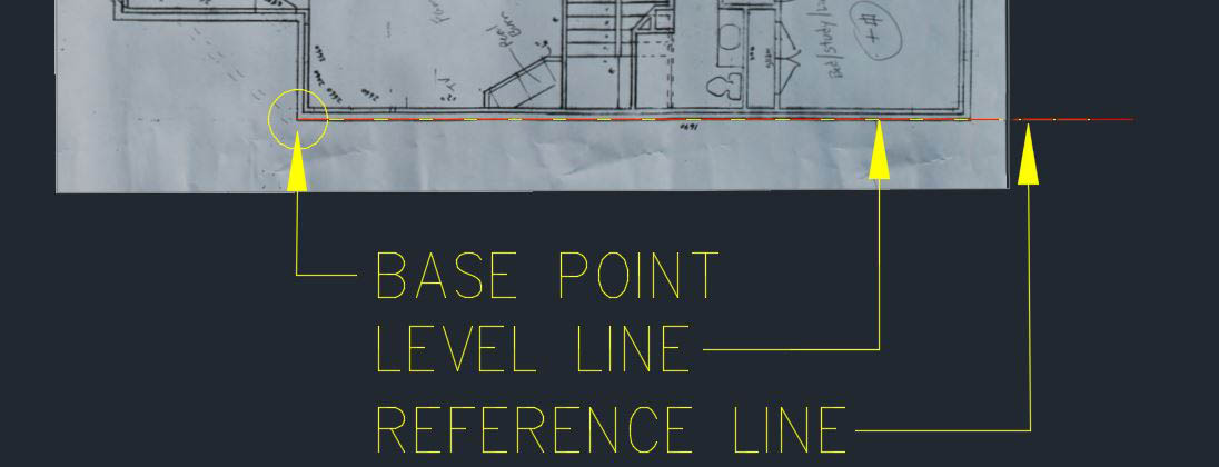
After rotation of image and reference lines
Now that the rotation procedure is done, let’s move on to the next step, scaling the image.
SCALING THE IMAGE USING A REFERENCE LENGTH
To scale the image to true real-world dimensions, we need to identify two points in the image which have a known real-world distance between them.
For example, in this sketch I know that the opening of the front door is exactly three feet (36 inches) wide. This is the actual, constructed width of the door opening.
On other projects, other examples of useful reference dimensions might be:
- You know a particular bedroom is exactly 12′-6″ wide.
- You know that a parking space is typically 8 feet wide in this neighborhood (useful with Google Maps satellite views)
- You know a kitchen countertop is about two feet wide.
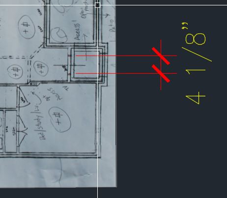
Door opening with dimension
I first create a linear dimension, clicking visually (since snaps don’t work on a raster image) to the two points on the reference object–in this case, the door opening.
Notice that the dimension displayed does not show the actual desired dimension. That’s to be expected. We brought the JPEG image in with a “guesstimate” scale of 100, knowing that we would correct it later.
For best accuracy, if the displayed dimension is “off” by a factor of 10 or more, you need to scale up the image by a factor of 10 and start this procedure again.
Next, I will mark the two points where the dimension’s extension lines cross the frame line of the image. I’ll call them Point A and Point B, and mark them with cyan colored circles. These will become our scaling reference points.
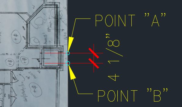
Scale reference points “A” and “B”
Here is the sequence to scale the image:
- Select the image, reference points, and dimension (I suggest using a green, right-to-left crossing selection window).
- Initiate the SCALE command. Type SC [ENTER], or in the ribbon go Home > Modify > Scale.
- The command line tells you to specify a base point. Using an intersection snap or center snap, click on Point “A.”
- The command line says Specify scale factor or … Click on the Reference option, or just type R [ENTER].

Command line showing scale reference option
- The command line now tells you to Specify reference length. To do this, click on Point “A” again, and then click on Point “B.” The distance between these points is the “before” reference length.
- The command line tells you to Specify new length. This is the desired, real-world distance between the points. Type the desired true distance and hit [ENTER]. in this case the desired length is 36 inches, so I type 36 [ENTER]. (This example is in USA Architectural units, so the default unit is an inch, and I don’t need to type the inch symbol.)
- BOOM! The image and the dimension are scaled up, and the dimension now reflects the correct distance between the two points. Happy dance time!
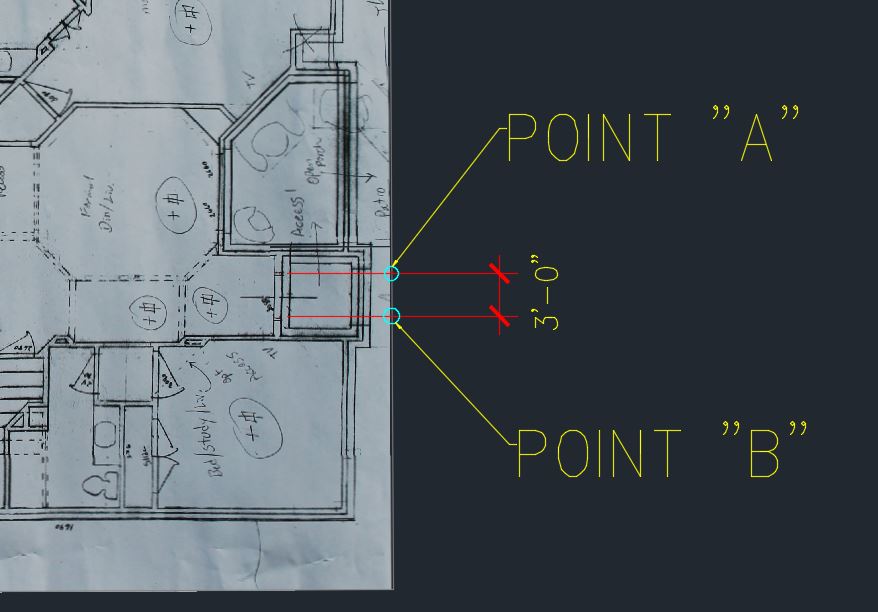
After scaling

YAY!
WRAP-UP
In summary, what we’ve done in these three posts is:
- We’ve converted a paper sketch into a high-quality raster image file. GO TO PART 1
- We’ve inserted the raster file into a DWG drawing file, scaled it roughly, and faded its brightness down to make it easier on the eyes. GO TO PART 2
- Finally, in this post, we’ve rotated and scaled the image using the Reference option, to make the sketch lines true orthogonal, and to make the image scale true 1:1 scale. It’s now ready for CADDing.
Hope this helps, and that you’ve enjoyed the post. Please leave a comment in the box below, share this with your friends, and share any comments or questions you may have on this topic.
See you next time, and as always, Keep On CADDing! 🙂
Mark