Today’s post will explore how to attach a raster image file, such as a photo of a sketch, as an underlay for use in creating a CAD drawing.
In the early part of any project, it’s not unusual to have your client, co-worker, or boss hand you a paper sketch that needs to be CADded.
This is often part of the process of taking an idea from its initial concept into a design, and later from the design into its physical reality.
In an earlier post, I discussed how to turn a paper sketch, drawing, or print into a raster file. To recap, the simplest way to do this is to take a digital photo of the sketch, or scan it using a scanner. Usually small drawings convert best using a scanner, but larger drawings require a camera. See the earlier post HERE.
If you have access to a large format scanner, that’s great. It’s best to adjust the resolution of the scan, so that the image file created (often a TIFF file) is not so HUGE that it slows down your computer.
Comparing formats for the underlay file
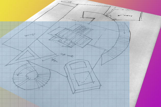
For my underlay in this post, I’ll use a JPEG format raster file that was created by taking a digital photo of a hand-made pencil sketch. The image is shown below.
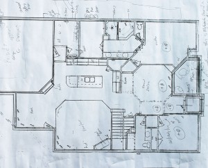
House plan sketch for underlay
PNG (Portable Network Graphics) and BMP (bitmap) format files work just as well.
TIFF files, such as from a large-format scanner, can slow down AutoCAD if they’re large.
PDF files: I try to avoid using PDF format files in AutoCAD underlays, since I’ve found that PDFs can decrease the speed of zooming and panning, and may cause other issues.
If you need to make a CAD drawing starting from a PDF file, I recommend converting the PDF file to JPEG format, using a program such as Adobe Acrobat.
As an alternative, you can simply take a screenshot of the PDF file image by positioning it to fill your screen and then hitting the Print Screen key on your keyboard.
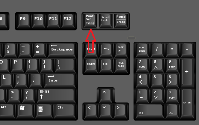
Keyboard with Print Screen button noted
Screen capture: Hitting the Print Screen key (see image at right) captures a “snapshot” of the current computer screen and stores it in the Windows clipboard. From there it can be pasted (using Ctrl-V) into an image editing program such as Windows Paint or Adobe Photoshop. From Paint or Photoshop you can save the image as a JPEG file.
The screen capture stored in the Windows Clipboard using PrintScreen can also be pasted directly into a CAD file (using Ctrl-V) as an OLE object. Sometimes OLE objects can behave in unexpected ways in AutoCAD, especially when printing. Since in this exercise the sketch image is only used as an underlay, you will most likely never need to print it. An OLE object might work fine.
Overall, I’ve had the best results using a JPEG file as an underlay.
Starting the CAD Drawing
Let’s open a new AutoCAD drawing using an appropriate template. In my standard office template, I’ve created a layer I call “Z_RASTER” which is intended for raster images such as this underlay sketch. The “Z_” prefix in the layer name is there to make the raster layer sort to the bottom of the layer list. This is for easy access, and also to keep it separate from the typical CAD-object layers. By having its own layer, the underlay can be quickly frozen or thawed when I want to view and judge my progress on the CAD drawing.
With the Raster layer set as the current layer, go in the ribbon to Insert tab > Reference panel > Attach button. (Alternately, for keyboard enthusiasts, just type ATTACH [ENTER].)
A dialog box will open called Select Reference File.
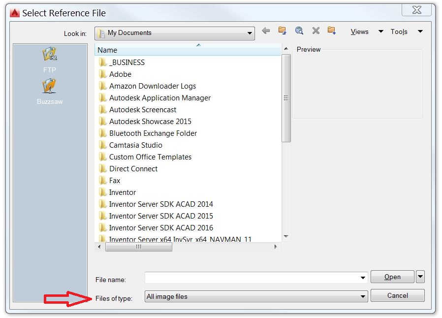
Select Reference File dialog box
First look in the bottom part of the dialog box at the “Files of type” selector. If it is set to “Drawing (*.dwg)” then you will not be able to see your JPEG file in the list above, no matter where you look. This setting acts as a filter for file types–only the file type(s) selected will be visible in the folders above.
Make sure the selector is set to “All image files” or “All files” to ensure that all image files will be visible in the list above.
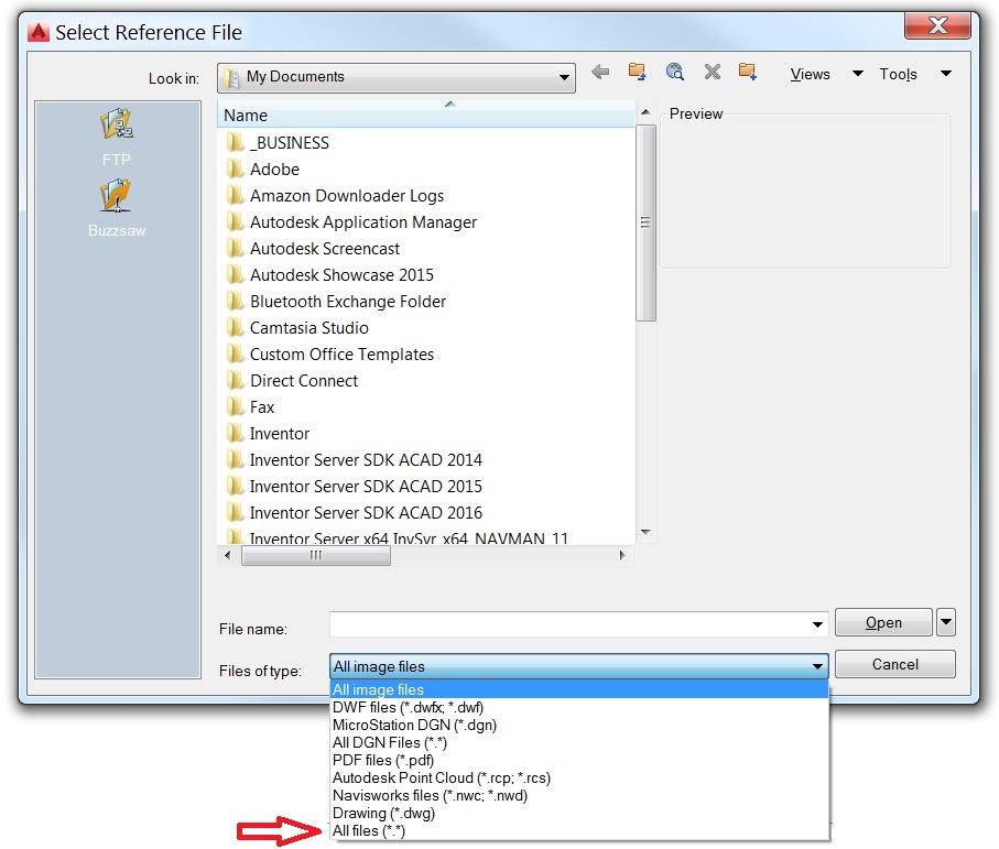
Dialog box expanded
Navigate through the folders to the image file that you intend to use as an underlay. Select the file by clicking on it, and click “Open.”
Inserting the Sketch
You’ll now see the Attach Image dialog box. It will show a preview of the sketch.
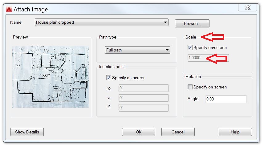
Attach Image dialog box
Under Scale, uncheck “Specify on-screen” and change the scale factor to 100. This is just a “guesstimate,” since we don’t yet know the exact scale factor needed to make the image “true” scale. It’s safe to say that it will probably be much closer to 100 than the default value of 1.0000. We will see how to make a more precise scale adjustment later.
Click OK. The image’s frame (a rectangle) is now following your pointer in the work area. Click anywhere to place the image.
Now select the image by clicking on its frame. You’ll see the ribbon change its appearance. If the sketch has a bright white background, I like to adjust the Fade setting to be about 50%. See image below.
The darker, faded background will make my CAD lines show up better when I’m tracing over the image. It also alleviates eye strain, I’ve found, by lessening the contrast between the image and the dark gray background.
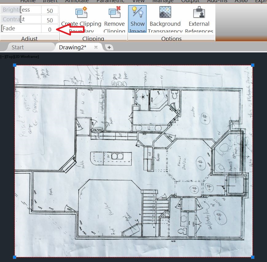
The Fade slider can be used to adjust the image brightness
Now that the raster image is placed in the work area, we’re ready to go to the next step, which is rotating and scaling the image.
In the next post, I’ll discuss rotating and scaling the image so that it is square with the screen and properly sized for tracing.
A video version of this post can be viewed by clicking below:
You can also find it at my channel on YouTube. Click HERE to go to my channel.
Until next time, I hope you’ll let me know your thoughts or questions by leaving a comment below.
Keep on CADDing! 🙂
Mark