Article 1 in a series
In this series we will explore the role of units in AutoCAD and develop a strategy for optimally setting up units in any drawing project. We will start from a 20,000-foot view and then progress to a more down-to-earth how-to discussion.
The AutoCAD 3-D Grid
What is the role of units in AutoCAD? First and foremost, AutoCAD uses units to keep track of the points that define every object in a drawing file.
What is a point? A point is a tiny geometric entity that has no length, no width, and no height. It does, however, have a specific location. Its location is defined within AutoCAD’s 3-D grid.
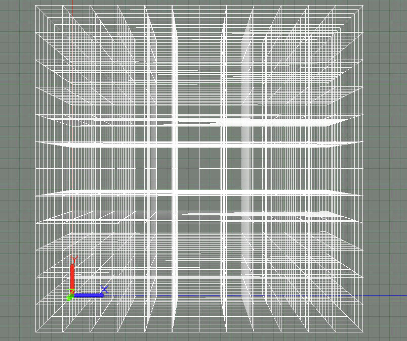
3-D Grid
The AutoCAD drawing universe is based on an imaginary 3-D grid. You can envision the grid extending to infinity, or at least beyond the extents of your project. Within this grid, AutoCAD places points. These points, in turn, define lines, circles, spheres, cubes, extrusions—all of the objects you put in your drawing. For example, a line is simply the shortest path between two points. A circle is defined by a center point and a radius length.
Every point’s location is defined by three coordinates: x, y, and z. Those coordinates are measured along three axes—also named x, y, and z. The measurements always start from a special point called the origin.
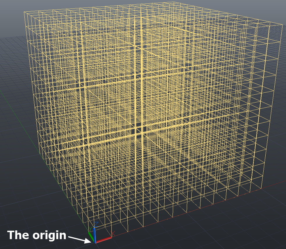
Where is the origin point located? It sits at the intersection of the x, y, and z axes. The origin is unique in AutoCAD’s system. Its coordinates are x=0, y=0, and z=0. Written in standard geometric language, the coordinates (x,y,z) of the origin point are 0,0,0.

3-D grid origin point
By the way, to see an audiovisual animation I made of the AutoCAD 3-D grid in motion, click HERE.
Setting the Origin Point
Where is the origin point located in the “real world?” The origin point’s location in relation to the real world is arbitrary. It’s up to you, the designer, to decide where it should be. In most architectural or mechanical drawings, the origin is set at the lower-left corner of the site, building or assembly, as seen in plan view. However, in a surveying or civil engineering drawing, the origin may be set to coincide with a benchmark. This is a fixed, physical, reference point which has been established near your site. See photo below.
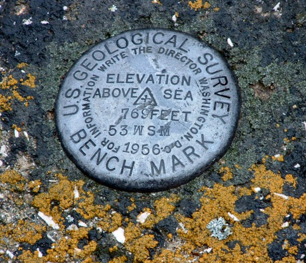
Example of a benchmark
You might say, “Okay, but the earth is round, not flat. How does AutoCAD account for that?”
Generally AutoCAD ignores that fact. Even when drawing a very large project such as an urban plan, we usually measure distances based on the x,y,z grid. On the other hand, if you work for Google Earth, your job may be to map our ever-changing planet. I’m sure you’re using a much more complex system than the Cartesian* x,y,z grid. If that’s you, please share your experience by leaving a comment below. I, for one, would love to know the system used for that.
Imagining the AutoCAD 3-D Grid In A Room
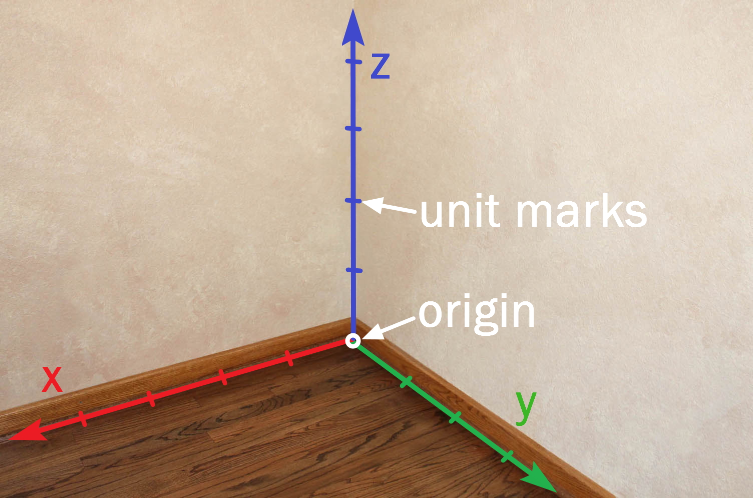
Room corner with origin
An example will help clarify. Let’s say I’m drawing a rectangular, boxy room and the furniture within that room. I’ll pick a corner of the room, say the southwest corner, at floor level, to align with the AutoCAD origin point. The x and y axes extend along the lines where the south and west walls meet the room’s floor. The z axis goes straight up from the floor to the ceiling, at the juncture of the south wall and the west wall.
All of the furniture, windows, and light fixtures in that room are created using points that AutoCAD measures from the origin point along the x, y, and z axes. The designer may not be aware of the x,y, and z values, but you can be sure that AutoCAD is keeping track of them!
Now imagine three large, super-thin translucent planes colored red, green, and blue. These planes are placed perpendicular to the x, y, and z axes. Next, choose a point in the room, let’s say a corner of a table top. You want to determine the coordinates of that point in space. How far do you need to slide the y-z plane along the x axis to “capture” or align with that point? That number becomes the point’s “x” coordinate. Repeat this action for the planes of the “y” and “z” axes, and the point is defined by x,y, and z coordinates. Conventionally, the “z” axis always measures the height of a point above the floor.
Now you’re starting to see the world as AutoCAD does. But wait—how do you communicate to the builder or manufacturer the distances that we measure on the x, y, and z axes? Two big steps north and five small steps east? An arm’s length each way and up to my waist?
Enter the Unit Type
That’s where unit types come into the picture. Before the designer has created a single line, AutoCAD has set up your drawing universe by establishing a 3-D grid, measured in abstract units. The designer must decide what real-world length unit to make equal to one AutoCAD unit. This decision will be based on three factors:
- Where you are located geographically,
- Where the construction site or manufacturing facility of your project will be located, and
- The type and scale of your project.
If you are designing a new microchip, your drawing unit will be different from that of someone designing a kitchen cabinet, or a building.
This all may seem obvious, but it forms a conceptual foundation for what’s to follow. Some day you might need to create or update a drawing template (DTE file) to use in your design business. This discussion will increase your confidence and mastery of the complex subject of drawing units. This will become clearer as we go forward.
Since this is getting a bit long, I’ll end here for this segment. Article 2 in this series will explore the effect of geography on project units, and address the question of which unit type is “best.”
Have a great day, and Keep on CADDing! 🙂
Mark
*For additional information on the Cartesian coordinate system, click HERE.