
Tip 1038

This article was selected for publication in CAD Digest
Text in AutoCAD dimensions can be puzzling. This post will cover some basic concepts and two different approaches to controlling the size of text in dimensions. Let’s start with some general guidelines:
Editing individual dimension objects
Text can be re-formatted or adjusted for an individual dimension object by selecting the object and then using the Properties dialog box. The Text section of the Properties dialog box is shown below. Changes made here have no effect on other dimension objects, and no effect on the dimension style. It’s just a one-shot modification.
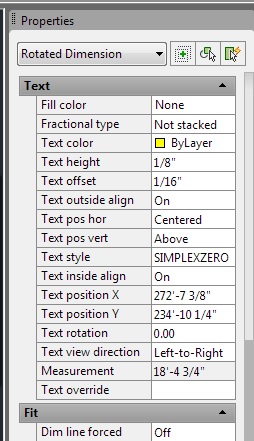
The Text section of the Properties box
Formatting dimension text using the Dimension Style Editor
On the other hand, text format changes made in the Dimension Style Editor affect all of the dimensions having that style. The change will affect existing dimension objects in your drawing, as well as future dimension objects created using that style. Here is a sample of the Text tab in the Dimension Style Editor.
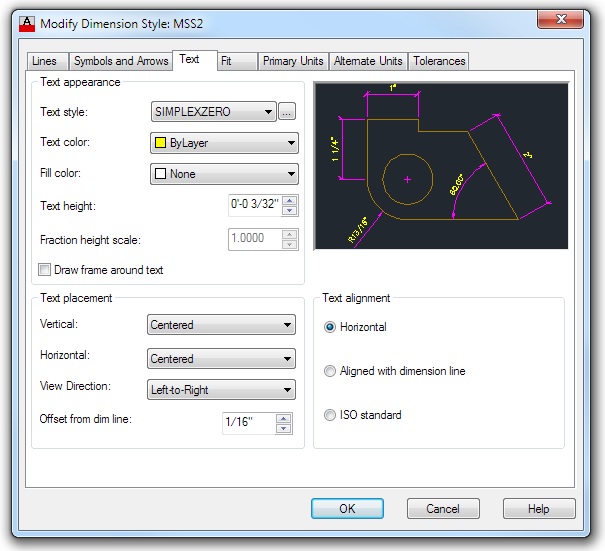
The Text tab in the Dimension Style editor
It’s a good idea to use a text style having an assigned height of zero (0) for the dimension text. This will make the dimension text change its height to match the current DIMSCALE setting when a new dimension object is created.
That’s why the text style in the above image is called “SIMPLEXZERO”. That’s a text style I created for dimensions, using the Simplex font set to have a height of zero in the Text Style Editor.
If the text style height was set to a non-zero number, say 9 inches, the dimension text would maintain that exact height in model space regardless of the DIMSCALE setting. This would not allow dimensions to automatically self-adjust for different drawing scales.
The One-DIMSTYLE-Fits-All Approach
In the image above, you’ll notice that the Text height is set in the Dimension Style Editor at 3/32″. This means that the text will automatically adjust itself to print on paper at exactly 3/32″ high when the current DIMSCALE is set to match the scale factor of the current drawing. For example, you would use a DIMSCALE of 96 for a 1/8″=1′-0″ scale drawing.
I set the current DIMSCALE by simply typing that command in the command line and then typing in the number I want for the current drawing task. When I start work on a detail or view at a different scale, I change the DIMSCALE again.
This allows the text in multiple views having different scales to match perfectly in the final printed sheet.
By the way, a dimension object, once created, retains the DIMSCALE that was current at the time it was created. You can see its DIMSCALE, and change it, by selecting the object and looking in the Properties box under the “Fit” category. The property item is called “Dim scale overall.”
I personally recommend this strategy. However, it’s not the only one worth considering.
The One-DIMSTYLE-Per-Scale Strategy
Some designers or firms use a different approach to sizing text (and tick marks or arrowheads) in dimensions. They create a separate dimension style for each scale of drawing or view that might be used. This is why you might run across dimension styles named “SCALE-96″ for use in 1/8” scale drawings, or “SCALE-24″ for use in 1/2″=1′-0” scale drawings.
In this strategy, you create one dimension style you like, then copy it a number of times, with different settings for the “Use overall scale of” field in the Dimension Styles > Fit tab, as shown below:
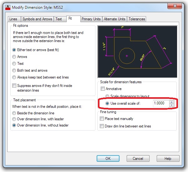
The Fit tab in the Dimension Style Editor
The value of 1 shown in the image above would be changed to 96 in the SCALE-96 dimension style for 1/8″ drawings, for example, and you would repeat and adjust for each scale needed.
When you go to the Dimension Style Selector in the ribbon and choose, for example, the SCALE-96 dimension style, AutoCAD automatically resets the current DIMSCALE to equal 96.
Personally, I think there are advantages and disadvantages to this approach.
The main advantage is that it is “easy-to-use,” in the sense that the CAD operator does not have to think about adjusting the DIMSCALE setting to match the scale of the current drawing or view.
Under disadvantages, I would list two:
- It requires a large number of dimension styles, which clutter up the drawing file and the DIMSTYLE list. This issue is multiplied if you maintain more than one dimension style for various types of work, such as an arrowhead style for site plan work, architectural tick marks for floor plans and such, and perhaps an inch-and-fraction dimension style for cabinetry drawings.
- If you ever want (or need) to make a change to your dimension style, you have to make the adjustment lots of times, which is an invitation for accidental discrepancies.
- It seems inelegant.
Please let me know your thoughts. I hope this helps to clarify some of the different options.
I hope you’ll sign up to receive future updates in the form below.
Keep on CADDing! 🙂
Mark
Related articles


How can I print this to keep for later reference?
Or all of the other Tips. We have just loaded up AutoCad 2014 3D and the Structural Detailing and I need all the help
I can get. Do I need pay per Tip or by month, please let me know, Thanks Tom
Tom,
Thanks for your question. I offer on-site consulting and training, which it appears might be helpful for you. I will send you an email directly to see if you are interested. Have a great day! Mark
Tom, Just enter your name and email in the “sign up” box to the right of the main page and you’ll receive an email notice with a link to each new post. Plus special offers. Or just check the box below the Submit Comment box when you send a comment. Your information will not be sold or shared with anyone, see our Privacy Policy by clicking the link on the sign-up form. Thanks! Mark