Part 2 of 2
This is a continuation of our tutorial in which we shared the Best CAD Tips Linetype Scale Matrix.
CLICK HERE to read Part 1 of the tutorial.
Why are my dotted and dashed lines not showing up dotted and dashed?
You can get a free download of the Best CAD Tips Scale Factor Table by joining our community. CLICK HERE TO JOIN
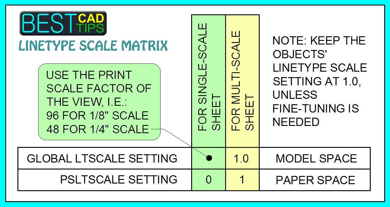
The Best CAD Tips Linetype Scale Matrix
Examples:
Here are some examples demonstrating how to use the Best CAD Tips Linetype Scale Matrix.
BONUS DOWNLOAD: If you’d like to download a free DWG file of this example, and use it to follow along as we go through the tutorial, just click on the link below:
CLICK HERE FOR DWG FILE DOWNLOAD.
1. Single-Scale Drawings
Let’s say you have a building plan which you intend to print at 1/8″ scale (1/8″ = 1′-0″). Here is a simple floor plan:
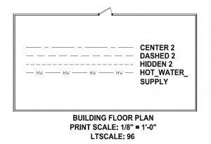
Floor Plan example
In this plan I have included four non-continuous linetypes:
- HIDDEN 2,
- DASHED 2,
- CENTER 2, and
- HOT_WATER_SUPPLY.
Referring to the Best CAD Tips Linetype Scale Matrix (above), look in the GREEN column to get the settings for a Single-Scale Sheet. You see that the LTSCALE setting should be the scale factor of the view (again, get your free Best CAD Tips AutoCAD Scale Table above). Below that, you see that the PSLTSCALE should be 0. Keep those in mind. We will first go to model space.
First, make sure you have drawn all of the lines in model space with an OBJECT linetype scale of 1.0 (which is the default). Select one of the lines and open the PROPERTIES palette (type CNTL-1).
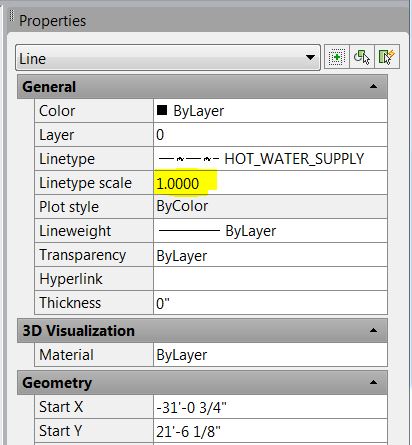
Properties box showing an object’s linetype scale
Ensure that the Linetype Scale setting for the selected object is 1.0000 as shown here. Check the other objects to be sure that they all have this same setting. Generally this is the setting you should have as the current setting when you create all lines in your drawing. Keep in mind that this OBJECT Linetype Scale setting, which relates to each object individually, is separate and distinct from the global LTSCALE setting, which effects ALL objects in model space.
The OBJECT Linetype Scale setting can be used to fine-tune the appearance of the lines, if needed. You can use the MATCHPROP tool to “paint” an object’s linetype scale setting from one object to another.
Now let’s set the global model space LTSCALE setting to match the drawing’s Scale Factor. Using your handy-dandy Best CAD Tips AutoCAD Scale Table, you find that for your 1/8″ = 1′-0″ scale floor plan, the corresponding scale factor is 96.
Now set the LTSCALE setting. With nothing selected, type LTSCALE [ENTER], then 96 [ENTER] to set the global LTSCALE setting in model space to 96. All of the lines in the 1/8″ scale view should display properly (in model space).
You may need to run REGENALL (the hotkey is REA) to refresh the display. This is often needed in both model space and paper space.
I like to print drawings to paper from paper space. Go to the layout tab in which you’ve set up the size of sheet that you want to print.
Type PSLTSCALE to see what the current Paper Space Linetype Scale setting is. By default, it is typically 1. Change it to 0 by typing 0 [ENTER]. Run REGENALL.
If the PSLTSCALE setting is 0, the non-continuous lines should display properly.
If it is 1, they will not display properly, but will look “solid” or continuous.
This is really all you need to know for a single-scale sheet. Simply set the model space LTSCALE setting to match the appropriate scale factor, then go to paper space and set the PSLTSCALE to zero (0).
2. Multi-Scale Drawings
It gets slightly more complex when you have a sheet of multiple views that have different scales.
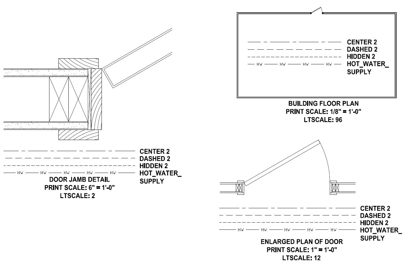
In this example, say you’ve drawn a floor plan as shown above at 1/8″ scale (1/8″ = 1′-0″), and you also want to display an enlarged plan of the door at 1″ scale (1′ = 1′-0″), and a jamb detail of the door at half-full scale (6″ = 1′-0″). Here are the three views:

Floor Plan of Building
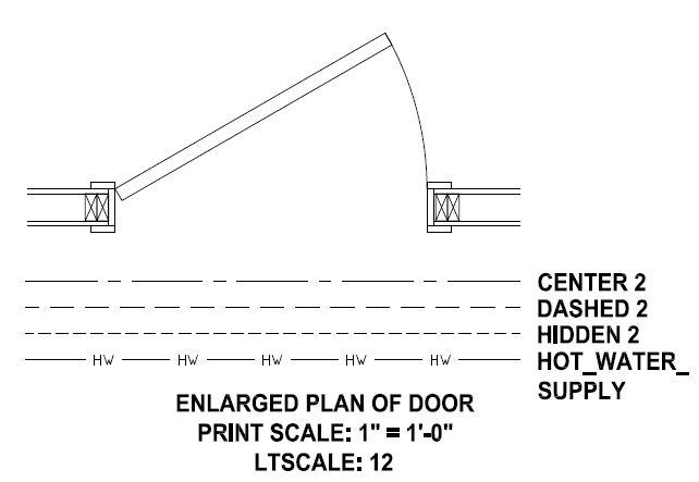
Enlarged Plan of Door
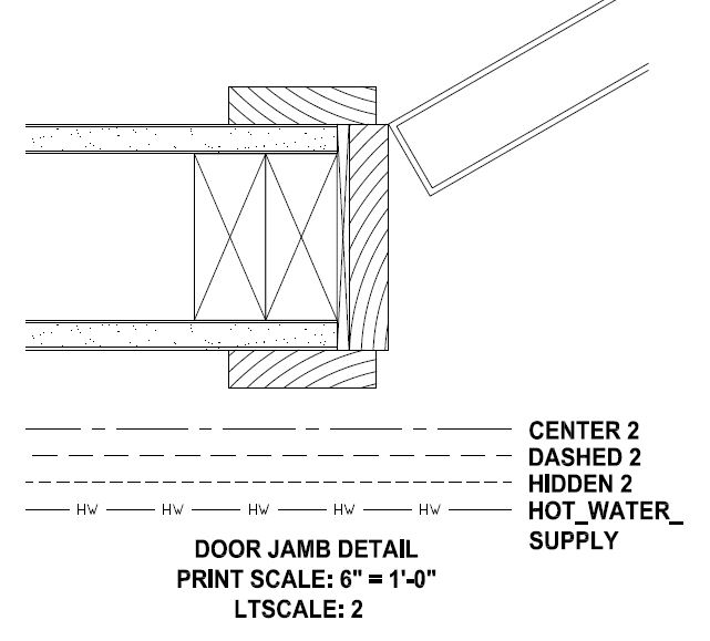
Door Detail
Let’s say you want to compose all three views on an 11″ x 17″ sheet, using viewports to control the different scales, and you want all of the non-continuous linetypes to read properly in all views on the sheet.
First, refer to the Best CAD Tips Linetype Scale Matrix above, and look in the YELLOW column for the Multi-Scale Sheet situation. I see that the LTSCALE in model space should be set at 1.0, and the PSLTSCALE setting in paper space should be set to 1. Keep those values in mind.
Draw all of the views in model space, using different scales. Again make sure the OBJECT linetype scales are all set to 1.o.
While you’re in model space, prepare for printing by setting the Linetype Scale to 1.0. Type LTSCALE [ENTER], then 1 [ENTER]. Next type REA [ENTER] to refresh the screen. All of the non-continuous lines will appear solid. This will look wrong at first, since the linetypes are not showing properly, but it is necessary in order to get the layout views in paper space to read properly.
Now go to paper space (11×17 layout tab) and type PSLTSCALE [ENTER], then 1 [ENTER]. Again type REA [ENTER] to refresh the screen.
Voilà! All of the lines in all of the views should read correctly.
See screenshot below of the multi-scale sheet with all of the linetypes showing correctly.
Sheet with Multi-Scale Views
If you’re like me and prefer to do your model space drawing and editing work with “correct” linetype visibility, you will need to bounce back and forth between a model space LTSCALE setting of 96 (or whatever is appropriate for the view you are working on) and 1.0 when it comes time to print the sheet in paper space.
Hope this helps! If you found this useful please leave a comment below.
Keep on CADDing! 🙂
Mark
Hi, Any chance of there being a metric version of your Scale Factor Table?